Next: Wall boundary conditions
Up: The CAA Methods in
Previous: Artificial Damping and Filtering
Fan noise is commonly considered the dominant noise component of modern high-bypass-ratio aero engines.
To accurately evaluate the sound propagation in an aero engine inlet and its far-field radiation,
the prediction methods must be capable of handling complex geometries,
including the spinner cross-section and accounting for basic mean-flow effects.
In general, fully three-dimensional numerical methods are required for the description of the sound
propagation in a duct. The main disadvantage is
that the 3D methods have high costs in both time consumption as well as the demand on computational resources,
especially for high frequency cases.
In an axisymmetric duct flow, the three-dimensional linearized Euler equations in a cylindrical coordinate system (x, r,
φ
)
can be chosen to describe this problem. However, under the assumption of an axisymmetric mean flow
and axisymmetric acoustic boundary conditions, the three-dimensional fluctuating quantities can be
decomposed into a Fourier series in the azimuthal direction. This yields a system of independent
two-dimensional (x, r) differential equations for each azimuthal mode m of the fluctuations.
Since tone noise in the inlet of aircraft engines is generally dominated by only a few components
at the blade passing frequency and its harmonics, it is computationally much more efficient to treat
these few two-dimensional Fourier components rather than to solve the full three-dimensional system.
In fact, the Fourier decomposition technique has found various applications in axisymmetric duct acoustics.
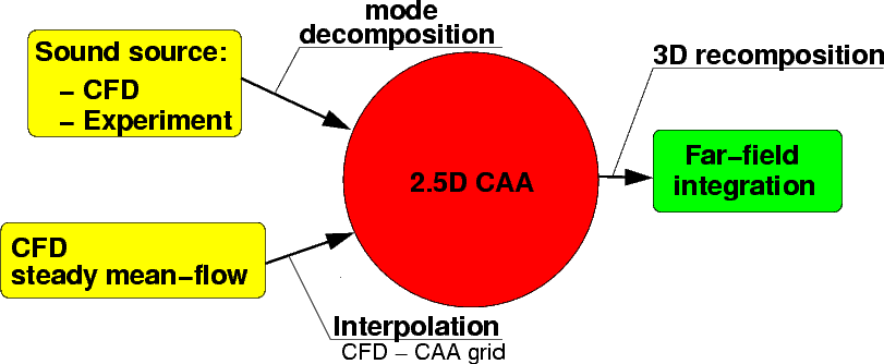
A sketch of the method to calculate a 3D sound field with this CAA-method is given below with the required input and the possible output.
For further details please refer to Schemel (2003) and Li et al. (2004).
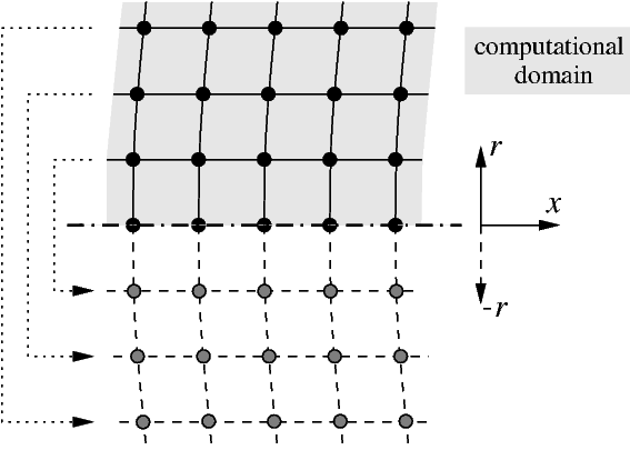
Two particular problems are associated with the boundary condition at the axis. Firstly, the singularity of the
cylindrical coordinate system can be solved by application of the derivative in r
replacing the ratio to r. The other problem is the boundary condition at the axis.
No fluid flows across the axis; the normal velocity components (v, w) are zero.
This leads to a wall condition at the axis, preferred by some authors.
However, the stability of the whole method may
be enhanced due to the central stencil at the axis. Such a solution
requires additional information below the axis
φ
=180 deg,
using which the boundary conditions for all variables can be formulated.
Next: Wall boundary conditions
Up: The CAA Methods in
Previous: Artificial Damping and Filtering
Charles Mockett
2005-03-18