SmaTrig - The smart 15-in-1 trigger for SLRs
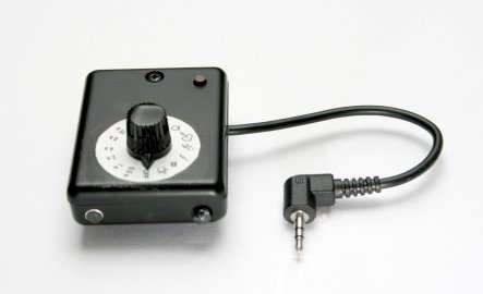
The SmaTrig is a compact, microcontroller based multi-function camera or flash trigger. Its 15 modes of operation make it come in handy in many situations. It is equipped with sensors for light and sound for capturing short-duration events. The only connection with the camera is the external trigger plug. There is no need to modify the camera in any way. The circuit is powered by an integrated coin cell.
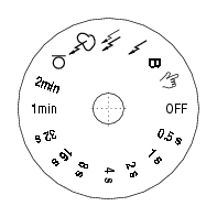
Trigger modes
- Manual trigger
- Bulb exposure (switch toggles state)
- Flash trigger
- 2nd flash trigger (TTL)
- Lighning trigger (uses mirror lock-up)
- Sound trigger
- Interval exposure 2.5 min
- Interval exposure 1 min
- Interval exposure 32 sec
- Interval exposure 16 sec
- Interval exposure 8 sec
- Interval exposure 4 sec
- Interval exposure 2 sec
- Interval exposure 1 sec
- Interval exposure 0.5 sec
Manual Trigger - This is the simplest mode of operation. The pushbutton works as an extension of the shutter button on the camera (only the fully pressed state is available).
BULB exposure - Pressing the pushbutton toggles the trigger between open and closed. Long time exposure is possible without holding the shutter button down continously. This function is practical for analog cameras where long exposure noise is not an issue.
Flash trigger - In this mode the camera is triggered directly by the photo-diode. This function can be used to trigger a servo flash or to build a light barrier with a laser pointer.
2nd flash trigger - In this mode the trigger responds to the 2nd flash in the sequence of two flashes such as the TTL flash sequence. The delay between the flashes must be less then 0.5 sec. This mode is primarily intended for servo flash control.
Lightning trigger - This function is similar to the flash trigger mode, but it's optimised to minimise the delay between lightning detection and exposure begin. This is achieved by utilising the mirror lock-up mode of the camera. In the case of the Canon EOS 400D the pre-releasing of the mirror reduces the delay from about 120 ms to 60 ms (see measurements) This should be fast enough to capture most lightning strike sequences.

- The camera is set to mirror lock-up mode by the user and the SmaTrig is in lightning mode.
- Pressing the push-button activates the lightning mode. The camera is triggered once and the mirror goes up. If a lightning is detected within 30 seconds, the camera is triggered for the second time and the exposure starts - a lightning was captured!
- After the exposure, for which a duration of 4 seconds is assumed, the camera is triggered again and the mirror goes up as in point 2. The trigger waits again for a lightning...
- If no lightning was detected within 30 seconds and there was no trigger impulse to the camera, the mirror is released automatically. One second later the camera is triggered again and waits for a lightning as in point 2...
- Pushing the button again deactivates the function.
Sound trigger - Sound exceeding a certain pressure level triggers the camera or the flash. This mode is perfect for high-speed photography. Popping balloons or champagne bottles are the typical trigger sources. In the example below the flash was triggered with SmaTrig while the cam was in long exposure mode.

Interval trigger - As the name implies, the camera is triggered periodically with nine different time intervals. Shooting time-lapse movies is the domain of this mode. This might be an example

To make the handling more convenient and save battery life most of the modes must be activated by pressing the push-button. Activation is signaled by the SmaTrig with a single beep. Pushing the push-button a second time deactivates the function again, this is signaled by a double beep.
How it works - Electronics
Schematics
SmaTrig is based on the ATtiny2313V microcontroller by Atmel. This small and versatile chip is a low power device which works down to 1.8 V. It is perfectly suited for battery operated equipment. A lithium coin cell was chosen as power supply. The schematic of the trigger circuit is depicted here
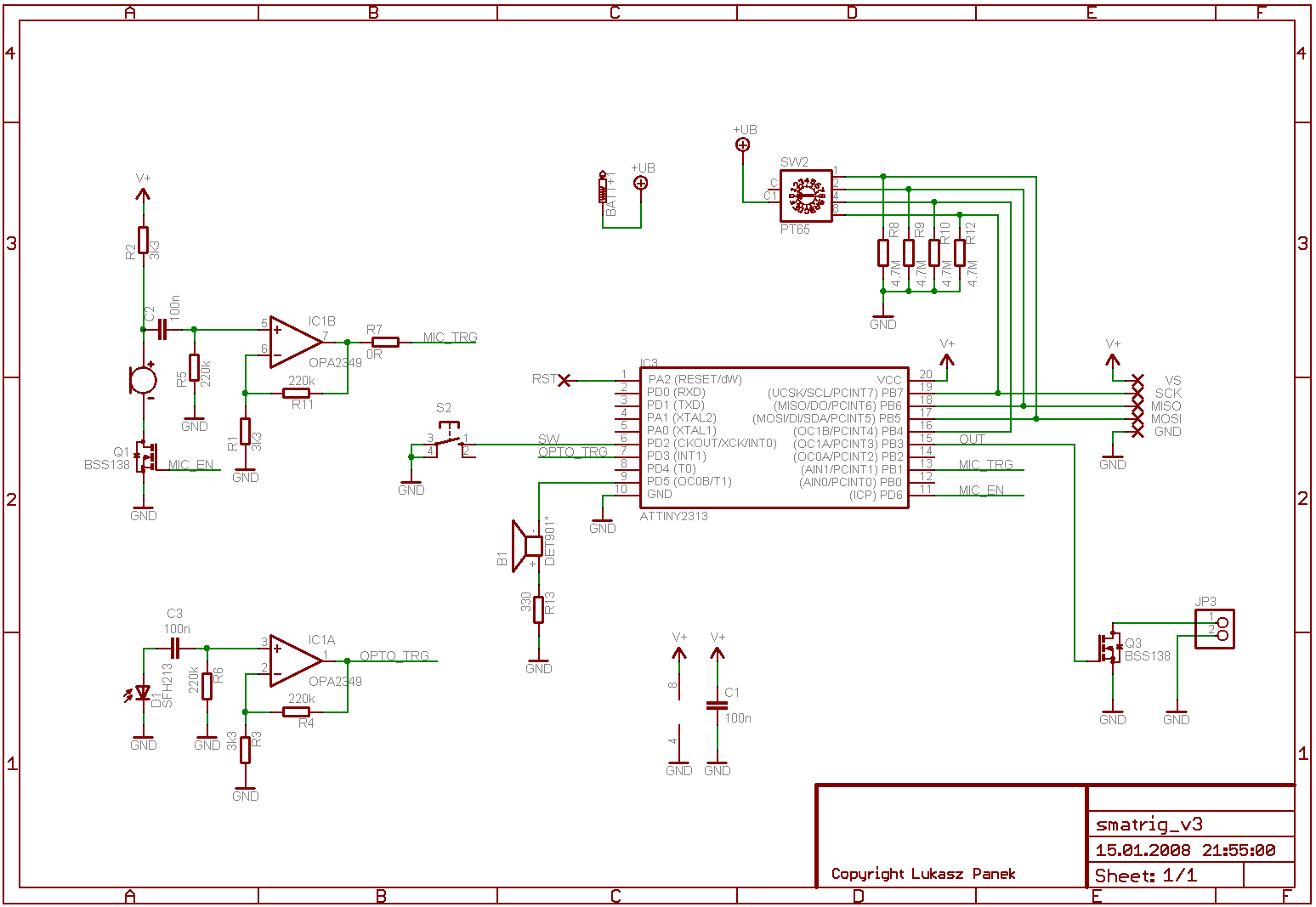
The controller is connected to a 4-bit code switch, a push-button, the triggering transistor and some sensor circuitry. The code switch allows to choose one of 16 modes of operation including power-off. The photo-diode and the mic signals are amplified via low power op-amps. The mic can be disabled by the microcontroller to save battery life. The circuit is supplied through the code switch connected to I/O pins of the uC. This unusual set-up uses the internal protection diodes of the I/O pins to source supply current to the chip and the rest of the circuit.
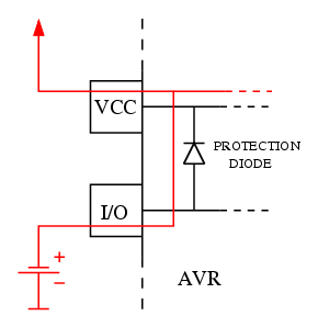
I discovered this effect accidently - it ruined my first design of the trigger. It just wasn't possible to switch it off because some I/O pins were connected to the battery and supplied the uC with 'parasitic' current. Keep in mind that a voltage drop of about 0.6 V across the protection diodes must be taken into account when supplying the chip this strange way. The minimum supply voltage of the uC rises form 1.8 V to about 2.4 V.
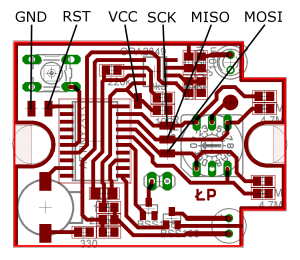
PCB
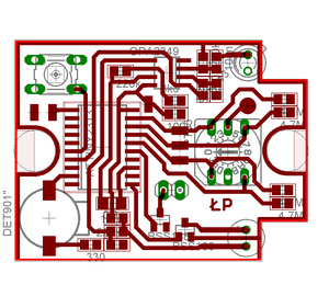
The one-sided board is designed with Eagle. The minimum path width of 24 mils allows for reproduction even with the crudest home-brew methods. I used a double sided FR4 0.8 mm board and left the unused side blank to provide some screening. Drilling is not necessary - the few through-hole mounted parts are mounted like SMDs.
Low power considerations
As the circuit is supplied by a lithium coin cell (2032), the power consumption should
be as small as possible. Ideally the battery should last for the life time of the
SmaTrig or at least for many years.
The electret mic turned out to be the main power
consumer with about 200uA supply current. Therefore I used a MOSFET to disable the
mic if not in use. The power consumption of the controller itself depends strongly
on the operation mode and the clock frequency. I used the internal 128 kHz oscillator
which is a good compromise of speed and power consumption. In power-down mode, the mode
used most of the operation time, the current ranges about a few uA.
In active or idle mode it can rise up to 50 uA. It's possible to control the clock of
the uC dynamically at runtime using the internal dividers, so each mode reduces the
clock to the possible minimum.
The op-amps are negligible with its 2 uA in total.
Assuming a battery capacitance of 80 mAh and an average supply current of 20 uA
a battery life of more than 8000 hours or about one year of continuous
operation can be expected.
Parts
I tried to use standard parts. The most exotic one is the OPA2349 op-amp. This low power amp has a supply current of just 1uA per channel. Fortunately it has the standard pinout and can be replaced by any other low voltage dual channel op-amp in an SO-8 package. The SMD buzzer may be also hard to find and can be replaced by a wired part. The four bit rotary code switch is a rather common part, a version with a spindle may be hard to find. I found one manufactured by Hartmann. Be sure to use the "V" version of the ATtiny2313. Only this version allows to work down to 1.8 V. The photodiode can be replaced by any daylight type. A high sensitivity type is preferable. The microphone is an electret type. For triggering with bursting balloons any type will do. Mics with bigger diameters are usually more sensitive, look for a high dB number. This number ranges usually between -70 and -30 and describes the output voltage per one Pascal of sound pressure. Negative dBs correspond to attenuation, thus -30 dB means that the output voltage is higher then for -70 dB.
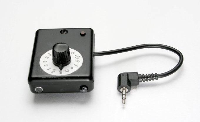
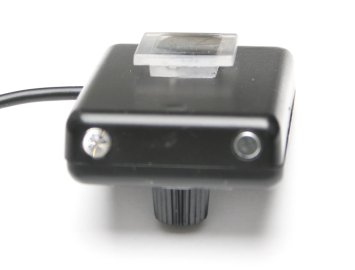
Enclosure
The circuit is mounted in a small pocket enclosure with an attached hot shoe adapter. The mic and the light sensor are installed in the direction of the lens. The hot shoe mount is simply made of two plastic plates glued together. It has no electrical connection to the camera.
I designed a label for the rotary code switch with XFig. It can be found in the download section of the page as a PDF-file.
Software
The controller was programmed in assembler. The source code and the hex file can be found in the download section of this side. To transfer the code into the uC I used a STK200 clone. The necessary wires have to be soldered directly to the programming pads on the PCB as shown in the picture below.
For programming the command line programming tool avrdude can be used.
I used the following options:
avrdude -p t2313 -c STK200 -i 500 -U flash:w:smatrig.hex
Important: The code wheel must be in position '4' to allow programming.
The reason is that the code wheel and the programming wires share some uC pins.
The option -i 500 must be used to slow down the programmer clock to allow
communication with the uC running at just 128 kHz.
The software was written to run properly with the power saving internal 128 kHz
oscillator. The device is shipped with the internal 8 MHz oscillator enabled,
so the fuse bits must be changed correspondingly before use. They are:
- efuse 0xff
- hfuse 0xdf
- lfuse 0xe6
avrdude -p t2313 -c STK200 -i 500 -u -t (set up communication with slowed-down clock)
>>write efuse 0 0xFF
>>write hfuse 0 0xDF
>>write lfuse 0 0xE6
After writing these values, the uC won't communicate with some programming tools due to the slow clock. If you need to restore the original clock settings of 8 MHz with enabled divider, set lfuse to 0x64
avrdude -p t2313 -c STK200 -i 500 -u -t
>>write lfuse 0 0x64
Now programming tools like PonyProg will work again.
Good luck!
Download
smatrig.sch - Eagle schematics
smatrig.brd - Eagle board
smatrig-parts.txt - Part list
smatrig-board.pdf - Eagle board as PDF
smatrig.asm - Assembler source code
smatrig.hex - Assembler hex file
smatrig-code-wheel.pdf - Code wheel label as PDF
smatrig-code-wheel.fig - Code wheel label for xfig
smatrig.zip - All files zipped together
Links
http://www.atmel.com/dyn/resources/prod_documents/doc2543.pdf - ATtiny2313 datasheethttp://download.savannah.gnu.org/releases/avrdude/avrdude-doc-5.5.pdf - avrdude documentation
http://www.lancos.com/prog.html - PonyProg, AVR programming tool
http://www.maxell.co.jp/e/products/industrial/battery/cr/index.html - 2032 lithium battery discharge curve