DIY Canon wireless remote control
This article describes how to build a low-budget AVR-controlled DIY infrared remote control for Canon cameras. To 'hack' the communication protocoll I reverse-engineered Canon's RC-1 remote control. This small device lets you trigger the camera instantly or with a delay of 2 seconds for a distance of up to 5 meters (~16 ft). It comes in very handy when taking long exposure pictures or for HDR photography. In bracketing mode the RC-1 lets the camera shoot a whole series of images at once!
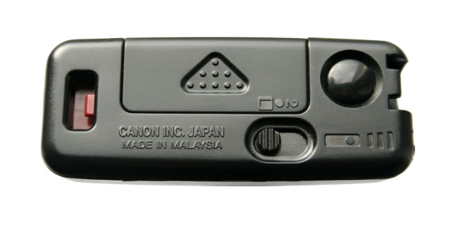
Canon RC-1 disassembled
To figure out the protocol I used an IR photo-diode first. Because of the bad signal quality I decided then to disassemble the RC-1 and measure the IR-LED voltage directly. I used the occasion and took some pics of the circuit.
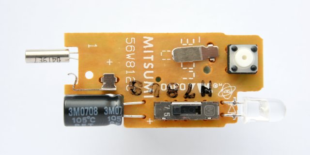
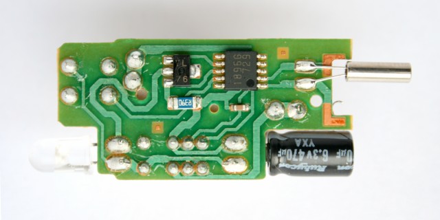
To all appearances the circuit is build around a quartz-controlled microcontroller with an additional transistor to switch the IR-LED. The supply capacitor is large enough to maintain the function of the remote control for a few shots with removed batteries.
Communication protocol
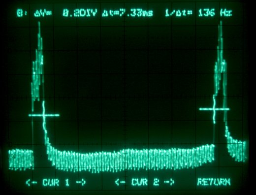
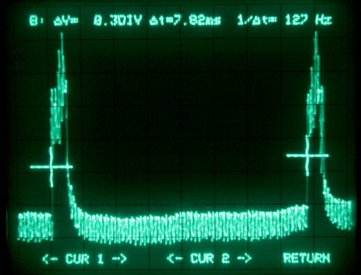
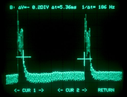
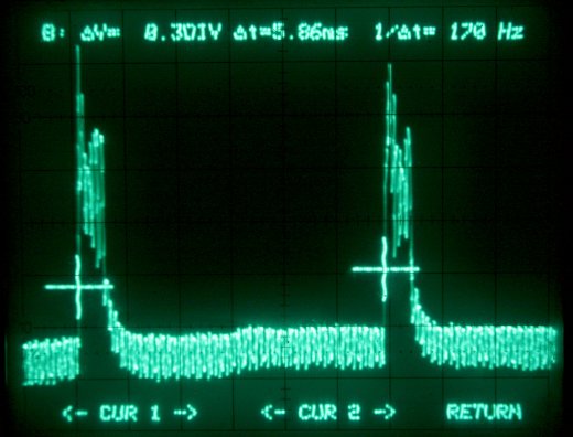
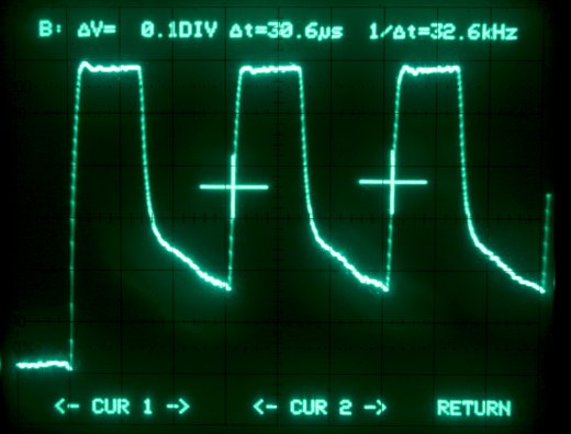
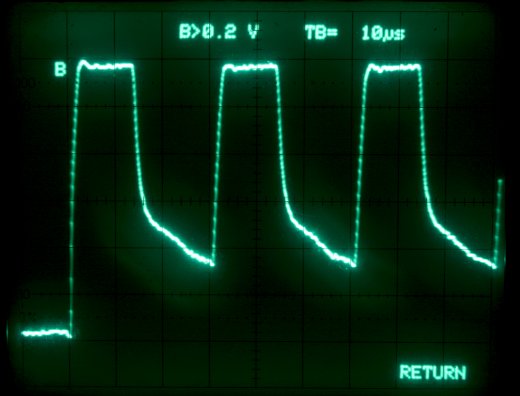
To the hobbyist's delight there is no communication protocol like the RC-5 code which most TV remote controls use. The signal send by the remote control consists of two identical bursts of pulses as shown on the pics below. To distinguish between the two possible modes of operation of the Canon RC-1, the delay between the bursts is changed. The signal shown in the oscilloscope screenshots below was captured directly at the IR-LED of the circuit. The overlaid noise in some plots is due to an internal oscilloscope problem.
Timing for instant trigger mode
Timing for 2s delayed trigger mode
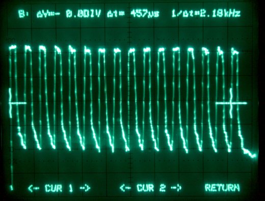
Pulse burst Timing
Timing and Tolerances
The signal timing of the original Canon RC-1 is listed in the table below. Having build my own remote control I could also find out the tolerance for each parameter. I used the Canon EOS 400D for testing.
| Parameter | Original RC-1 | Tolerance |
|---|---|---|
| Num. of pulses | 16 | 9 - 22 |
| Burst frequency | 32700 Hz | 29800 - 35500 Hz |
| Delay for immediate trigger | 7.33 ms | 7.0 - 7.7 ms |
| Delay for 2 s delayed trigger | 5.36 ms | 5.1 - 5.7 ms |
The clock frequency is very close to the standard watch crystal frequency of 32768 Hz. The experiments were made from a very short distance. I didn't test the sensitivity reduction for the deviating parameters and didn't test them in combination.
AVR implementation
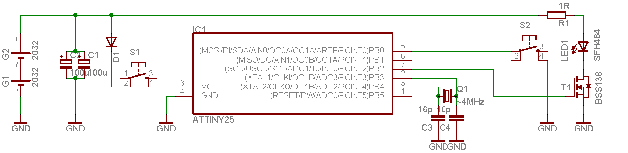
The first circuit I made was based very much on the original Canon (or Mitsumi, see image above) design. After I got it working, I simplified the schematics successively to reduce the part count and make it more easy to build. The schematics of the initial version is here. The simplified version is shown in the picture below.

I was able to trigger an Canon EOS 400D from more then 5 meters (~16 ft) with both
versions, though the simple version had more failed trigger attempts.
The "high-end" version uses a crystal oscillator to provide a precise clock
to the microcontroller. The IR-LED is driven by an NMOS transistor allowing higher
current then the controller outputs can source.
The controller is supplied via a diode to reduce the supply voltage
below the recommended maximum of 5.5 V.
In the simplified version the crystal oscillator was replaced by the internal 8 MHz oscillator, saving three external parts. The disadvantage of this solution is that the frequency is drifting slightly with the supply voltage and temperature. Details can be found in the "Electrical Characteristics" section of the Attiny25 data sheet. The most radical simplification was the elimination of the transistor. I found out experimentally that driving the IR-LED directly from paralleled microcontroller pins is powerful enough to trigger the camera from about 5 meters (~16 ft). Finally the voltage reducing diode has been dropped increasing the supply voltage to the "absolute maximum" value of 6 V. I don't recommend to leave the mode selector input pin unconnected in the simplified version. I had some sporadic shots in the wrong mode.
The program was written in C and compiled with the avr-gcc compiler in the AVR-Studio. The _delay_ms function was used to generate the delays. After applying power to the controller, pin PB0 is tested for its level. If the level is high (pin not connected, internal pull-up active), the instant trigger signal is emitted. If the pin is tight to ground, the delayed trigger signal is send. After sending the pulses, the microcontroller is put in power-down mode to reduce the power consumption to the minimum. When the push-button is released, no current is drawn from the battery, except the leakage current of the capacitor. A high quality cap should be used to keep this current low. The LED output signal is present on pins PB1 and PB2. The pins should be used in parallel if driving the LED directly as in the simplified circuit version. For some inexplicable reasons I wasn't able to parallel more then two pins. Before compilation, the microcontroller clock frequency must be specified in the c-file header according to the oscillator used. If the internal 8 MHz oscillator is used as clock source, an F_CPU of 7.9 MHz is a good choice. The reason for the difference is the voltage drift of the internal RC-oscillator. The nominal frequency of 8 MHz is specified for a supply voltage of 3 V. It's decreasing slightly for higher supply voltages. The dependence is documented in a diagram it the data sheet of the controller.
#define F_CPU 7900000 // 7.9 MHz #include#include #include #include #include #include #define HPERIOD 0.01524 #define RATIO 0.4 #define NPULSES 16 #define LEDOFF 0b00000001 #define LEDON 0b00010111 int main(void) { uint8_t i; DDRB = 0b00010110; // pin PB0 is input, pins PB1 and PB2 are output PORTB = 0b00000001; // pull-up for input pin PB0 asm volatile ("nop"); asm volatile ("nop"); if ( PINB & (1<<PINB0) ) { for(i=0;i<NPULSES;i++) { PORTB = LEDON; _delay_ms(HPERIOD); PORTB = LEDOFF; _delay_ms(HPERIOD); } _delay_ms(7.33); // instant for(i=0;i<NPULSES;i++) { PORTB = LEDON; _delay_ms(HPERIOD); PORTB = LEDOFF; _delay_ms(HPERIOD); } } else { for(i=0;i<NPULSES;i++) { PORTB = LEDON; _delay_ms(HPERIOD); PORTB = LEDOFF; _delay_ms(HPERIOD); } _delay_ms(5.36); // delayed for(i=0;i<NPULSES;i++) { PORTB = LEDON; _delay_ms(HPERIOD); PORTB = LEDOFF; _delay_ms(HPERIOD); } } set_sleep_mode(SLEEP_MODE_PWR_DOWN); sleep_mode(); }
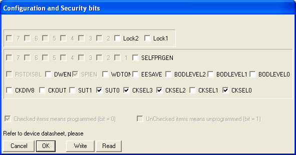
I used PonyProg to copy the hex-file into the controller and set the fuses. The fuse settings can be copied from this screenshot
| C source code | canon_remote.c |
| hex file | canon_remote.hex |
By the way, most digital cameras are sensitive to infrared light in the preview mode, so you can see IR-diodes blinking on the display. This might be helpful for basic debugging of the remote control circuit.
Links
http://www.lancos.com/prog.html - PonyProg, a nice AVR programming tool
http://www.atmel.com/dyn/resources/prod_documents/doc2586.pdf - Attiny25 data sheet