|
One of the major handicaps of present scientific and commercial CFD codes is caused by the available set of wall boundary conditions. Usually users can choose between two standard approaches: the first is a so called "high Re" boundary condition that assumes a logarithmic low-of-the-wall for the wall-adjacent cells and the second is a "low Re" boundary condition which resolves the entire boundary-layer including the sublayer with a very fine mesh. Unfortunately both require specific mesh properties, that strongly depend on the flow field. Consequently the user needs to know details of the flow in advance when he creates his mesh. To overcome this problem a basic formulation for a universal wall boundary condition is described here. The new method is based on the "high Re" boundary condition. This standard approach is extended by blending to a "low Re" boundary-condition in regions were the local grid-resolution provides small distances to the wall. The presented blending procedure allows the method to adapt itself to the local flow regime without any extra user input. The new universal boundary condition therefor has no specific requirements to the near-wall grid resolution and is applicable to 2D as well as 3D flows. As the new method promises to be mesh-independent it simplifies the mesh-generation process and might be an important improvement for CFD applications in industrial flows. Grotjans and Menter [4] presented a similar approach based on the wall function formulation that also provides universal meshes but always causes the same disadvantage as the high-Re formulation. The new method is implemented and tested at two simple 2D flows: a turbulent channel flow of Kim et al. [6] and the ONERA-A airfoil flow at maximum lift condition. Additionally the method was already applied to other airfoil flows, e.g. wall-mounted wing by Devenport and Simpson [3], the three-dimensional wing in a wind tunnel from the GARTEUR AG29 investigation [8], the transonic RAE2822 airfoil [7] and the A310 three-element high lift configuration. The new approach will provide conditions for mean momentum and turbulence properties for the wall-adjacent cells. A blending function between the high-Re-boundary-condition is introduced that is based on the nondimensional distance to the wall:
The expansion is converging very fast for small arguments.
Whereas for large arguments convergence is much smaller than for the
The wall shear stress is required to solve the momentum equation. To determine this property an iterative algorithm is introduced that need to be solved pointwise at each single iteration. The wall shear stress or the shear stress velocity must be stored for the next iteration. In addition to the blending of U+ all turbulent quantities have to be handled in a similar way. As for both the low-Re and the high-Re formulation the same Neumann-type boundary condition for the turbulent kinetic energy can be used, it is not modified
Additionally the production of turbulent kinetic energy is manipulated in the wall-adjacent control volume (marked by the index P)
The boundary condition for the second turbulent
quantity is reduced to a boundary condition for the turbulent length-scale
which can be applied to an equation for the dissipation rate
based on the turbulent Reynolds number
Rek.
The parameter
A universal boundary condition for Spalart-Allmaras [10] type one-equation model is given by the same method. In combination with this new b.c. it is recommended to use the Edwards modification [2] of the Spalart-Allmaras model due to its improved stability in the near wall region. Problems can occur in the case of very large quantities of Y+ > 400 and the eddy-viscosity has to be limited.
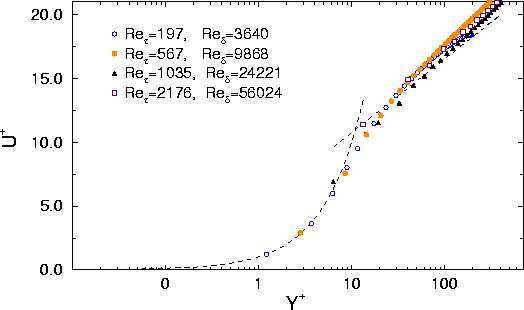
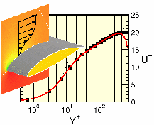
For basic validation the new boundary condition is applied to a simple turbulent channel flow. In this case changing the inflow Reynolds-number at a given mesh can easily modify the near-wall mesh resolution. High Reynolds-numbers will raise the nondimensional distance. By applying the new hybrid boundary condition the
velocity profile in the channel flow can be predicted with high
quality for a wide range of Reynolds-numbers. Figure 1 shows the
results obtained by a Wilcox
Figure 1: Nondimensional velocity
in a turbulent channel flow for different
Reynolds-numbers, obtained by hybrid wall boundary condition and
Wilcox
Figure 2: Turbulent kinetic
energy and shear stresses in a turbulent channel flow for different
Reynolds-numbers, obtained by hybrid wall boundary condition and
Wilcox In Figure 2 velocity, turbulent kinetic energy and
shear stresses are plotted for different Reynolds numbers and different
mesh resolutions respectively. The results prove that at least for
this simple flow the mesh influence completely vanishes by applying
the new universal boundary condition. Nevertheless the insufficient
representation of k compared to DNS by Kim, Moin and Moser
[6] can not be improved. Similar
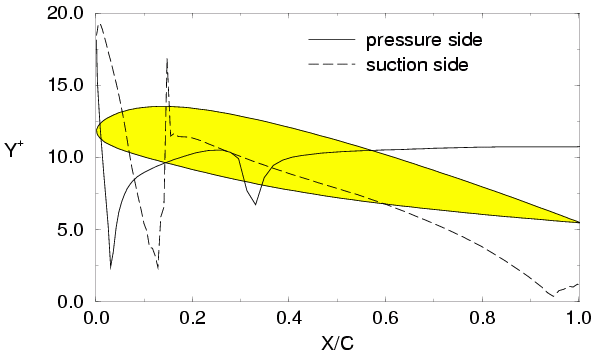
plots can be provided for In the following validation test case the combined influence of the new boundary condition and the numerical mesh in a crucial flow situation will be studied. The flow around an ONERA A-airfoil at Re = 2x10⁶, Ma = 0.15 and 13.3° angle of attack features a laminar separation bubble with turbulent reattachment combined with turbulent separation in the region close to the trailing edge. As simulations of this test case are very sensitive to details of the turbulence mesh it is a proper test for the new boundary condition [5]. Investigations are focussed on the Spalart-Allmaras model that is known to produce satisfying result for this flow. Transition is fixed at x/c = 0.12 on the upper and x/c = 0.30 at the lower surface. According to older investigations an adapted 22000 cell mesh (LG) is used that provides a maximum distance to the wall in the first control volume of Y+ < 1.3. Results of this mesh are compared to those obtained from a modified mesh (HG) with a nondimensional distance plotted in Figure 3. It varies from Y+ = 2 to Y+ = 20 with the same number of cells.
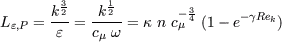
Figure 3: Near wall Y+ distribution of the high-Re mesh (HG) for the ONERA A-airfoil
Results obtained on the two meshes with different boundary conditions are plotted in Table 1. On the LG mesh results of the universal and the low-Re b.c. are identical therefore only the latter is plotted. Figure 4 and 5 show pressure distributions and skin-friction for the different boundary conditions on the HG mesh compared to results on the fine LG mesh. The latter results are in good agreement with the experiments capturing both separations with correct size. As expected the capability of predicting pressure induced separation dramatically drops with the coarser mesh HG. The universal boundary (HYB) shows superior results compared to the standard wall function formulation but suffers from an overpredicted shear stress in the leading edge regions. According to be specific Y+ distribution a difference between the universal and the high Re boundary condition only occurs downstream of x/c=0.4. The results obtained by the low-Re boundary condition on the HG mesh have to be handled with care. Velocity profiles and boundary-layer thickness seems to be superior to other results but the skin friction at the transition location is underpredicted and is very close to flow separation in the leading edge region with catastrophic result for the entire flow field. The new hybrid boundary condition is able to lead to more reliable results and improves the stability of the method at least for this particular flow. 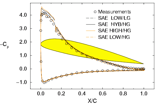
Figure 4: Pressure coefficient for ONERA A-airfoil 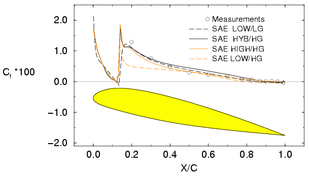
Figure 5: Skin friction coefficient for ONERA A-airfoil
|
 and
and