


Next: About this document ...
Up: J26222
Previous: Acknowledgments
Figure 1:
Flow around generic wing-body configuration - streamlines and pressure coefficient in three
selected wing sections
 .
.
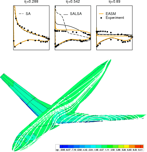 |
Figure 2:
Flow around Onera A airfoil (
 ,
,  ,
,
 )
velocity and shear-stress profiles on the suction side.
)
velocity and shear-stress profiles on the suction side.
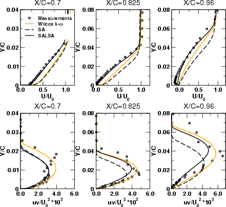 |
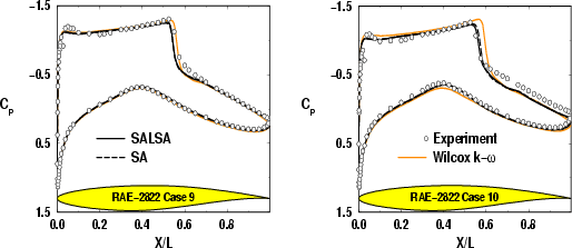
Figure 3:
Transonic flow around RAE-2822 airfoil (Case 9, left:
 ,
,  ;
Case 10, left:
;
Case 10, left:
 ,
,  ,
,
 ) -
distribution of pressure coefficient.
) -
distribution of pressure coefficient.
 |
Markus Schatz
2004-02-10