Next: CAA Approaches for the
Up: Numerical Simulation of Sound
Previous: Numerical Simulation of Sound
For the numerical simulation of sound propagation and radiation an aero-engine can be divided
into regions corresponding to different requirements for physical modeling and numerical treatment.
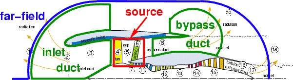
Fig. 1 shows a sketch of a typical aero-engine in which the different simulation regions are marked.
Figure 1:
Simulation Regions of an Aero-engine1
|
|
Considering the differing physical features in these regions the following modeling and numerical treatment techniques are adopted:
The source region contains the fan and the outlet guide vanes which generate noise both
from the rotor alone and from rotor-stator-interaction. To capture these effects, this region is
modeled by the Navier-Stokes equations which are solved numerically with a CFD method.
For an accurate reproduction of acoustic properties such as the dispersion relation, a relatively high resolution
is required, making
this kind of simulation very expensive. Therefore the physical domain modeled in this manner is kept as small as possible.
As the objective of this paper is the simulation of sound propagation and radiation, the source region
will not be considered further.
The duct regions span both the intake upstream of the source region as well as the bypass duct.
These regions are characterized by a steady mean flow and influence of the walls on sound propagation.
The sound propagation can be modeled by disturbance equations such as the linearized Euler
equations (LEE). For the numerical solution, a Computational Aeroacoustic (CAA) method is used. Such
CAA methods are based on discretization schemes optimized for acoustics. The optimizations reduce
the required resolution and therefore the numerical effort compared to standard CFD methods. (see section 3)
The far-field is free of sources and walls and their corresponding influences on the sound propagation.
Thus the region can be modeled with an acoustic analogy. Due to the limited number of required far-field observers for directivity plots,
the use of an acoustic analogy based integration method is much less
expensive than the field methods in the source and duct regions. The Ffowcs Williams & Hawkings (FWH) acoustic analogy
is especially well suited because it allows non-uniform flow through the exchange surface. This means that the interface between
the duct and the far-field region can be located closer to the intake. (see section 4)
Next: CAA Approaches for the
Up: Numerical Simulation of Sound
Previous: Numerical Simulation of Sound
Norbert Schönwald
2005-11-02